Specifications

SPECIFICATIONS:
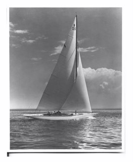
Designed and built by William Fife III
Year Built: 1929
LOA: 47'
Waterline: 30' 6"
Beam: 8'8"
J: 14' 9"
Displacement: Rated Lloyds @ 9 tons
Hull: Original tight seamed mahogany, carvel planked.
Interior: Original varnished hull, minimal accommodations per class rule
Frames:
100% Original: Rock Elm bent frames
100% Original: Rock Elm bent frames
95% Original: Sawn Oak
5% Of sawn frames replaced with Locust
Frames are laid out in series on about seven inch centers. Every third fame is a larger, grown, sawn oak frame with two rock elm frames between.
(%s are approximate, see photos and details in blog)
Modern aluminum mast:
Excellent condition
Measured to rule.
Stainless rigging
Imron coating over epoxy primer
Traditional Wood mast (no longer in service):
Excellent condition
Oregon Pine
Hollow
Short of the rule by a few inches
Custom fittings, all chromed bronze
Deck:
Cold molded in cedar for strength
Underside of deck is beveled cedar sprung in same
dimensions as original.
Beams:
Original beams are spruce
Beams replaced from back of cockpit to front of cabin
in spruce and Oregon Pine. (Oregon Pine replaces the
original Larch beams)
Cabin:
Cold molded for strength in cedar and mahogany
Underside of deck is beveled cedar sprung in same
dimensions as original.
Beams:
Original beams are spruce
Beams replaced from back of cockpit to front of cabin
in spruce and Oregon Pine. (Oregon Pine replaces the
original Larch beams)
Cabin:
Cold molded for strength in cedar and mahogany
Winches:
Main: 3 speed Lewmar
Main sheet: 2 speed Barlow
Trimming: 2 speed Barlow
Running backs: 2 speed Anderson self tailing
All details of her restoration are outlined in the this blog.
Labels: Specifications
posted by Classic Wooden Boat Restoration at 3:30 PM
0 comments
![]()
![]()


.jpg)


 To keep her shape, I installed a new deck beam between the cabin and the cockpit. This beam is notched into 2 new beam shelves of the same dimensions as those spreading the load at the mast.
 In 1991, I built a shop just the right size to house


